Charging lithium batteries safely
 |
| Testing the module, 3 18650s charged to 4.18v |
The design of the module consists of four seperate TP4056X ICs that charge up to four lithium batteries individually, I've set the maximum charge current per battery to 600mA.
Before I made this module I considered the readily available TP4056 modules, but I could not find anything that could charge four batteries, had the correct cutoff voltage of 4.2 and used high quality components, it turns out nearly all the modules on Ebay are TC4056, this has a questionable cutoff and poor tolerances. I also did not need the additional protection ICs as I would make my own protection module which needed to be seperate.
The video below is of the first iteration of the module, the circuit and components are all the same.
The components
I opted for the TP4056 IC as this required the least amount of discrete components whilst offering safe charging. The version of the TP4056 I went for was TP4056X, its main difference is; better regulation, better accuracy and better thermal dissipation. The package is SOP8, so not too difficult to solder and there is a thermal pad on the bottom.
I used a 2W 0.5Ω resistor to drop between 0.25V and 0.3V volts, this helps reduce the amount of power needed to be dissipated by the TP4056X.
All other components are standard 1% metal films resistors with a temperature coefficient of 100ppm or better. Capacitors are X7R.
When I tested this, the cutoff was at about 4.18v, which is perfect.
The schematic
 |
| The scematic consists of four seperate chargers. |
There is not much to say as it is such a simple circuit. The resistors for the LEDs need to be selected for different types of LEDs and brightness.
The RPROG (Rn-3) resistors were calculated to give about 580mA of charge current per battery. This helps keeps the power dissipation down of TP4056X.
The calculations
RPROG resistors
RPROG (Rn-3) resistor selection calculation, all results have a tolerance of ±10%:
VPROG = 1.1 V
VPROG
IBAT = ________ x 1100
RPROG
1.1
IBAT = ________ x 1100 = 600 mA
2000
We can see that a resistor value of 2000Ω produces a charge current of about 600 mA.
If you know what charge (IBAT) current you want, you can calculate the RPROG like this:
1100
RPROG = ______ (±10%)
IBAT
1100
RPROG = ______ = 1833 Ω
0.6
The table below shows some resistor values and the associated charge current, there is a tolerance of ±10%:
|
RPROG(K) |
IBAT (mA) |
|
30 |
50 |
|
20 |
70 |
|
10 |
130 |
|
5 |
250 |
|
4 |
300 |
|
3 |
400 |
|
2 |
580 |
|
1.6 |
690 |
|
1.4 |
780 |
|
1.2 |
900 |
|
1.1 |
1000 |
VRCC resistor
VRCC (Rn-4) selection
We calculate the voltage dropped by this resistor using ohms law, we know that 600mA or current will be flowing through the resistor:
V = I x R
V = 0.6 x 0.5 = 0.3 V
0.3V is dropped by this resistor, this mean the TP4056X has less power to dissipate.
Next we check to see how much power the resistor will dissipate:
P = I x V
P = 0.6 x 0.3 = 0.18 W
0.18W is dissipated by the resistor, I decided to use a 2W resistor as there was plenty of space on the rear of the PCB.
TP4056X dissipation
To work out the maximum power dissipated by the TP4056X, we can work it out by knowing the minimum battery voltage.
Lets assume the following values:
VBAT = 3.2V
VCC = 4.6V
RVCC = 0.3V
IBAT = 0.6mA
PD = VCC - VBAT - RVCC * IBAT
PD = 4.6 - 3.2 - 0.3 * 0.6 = 0.6 W
The maximum power dissipated by each TP4056X is about 0.6W, this power goes down as the battery voltage increases.
The PCB
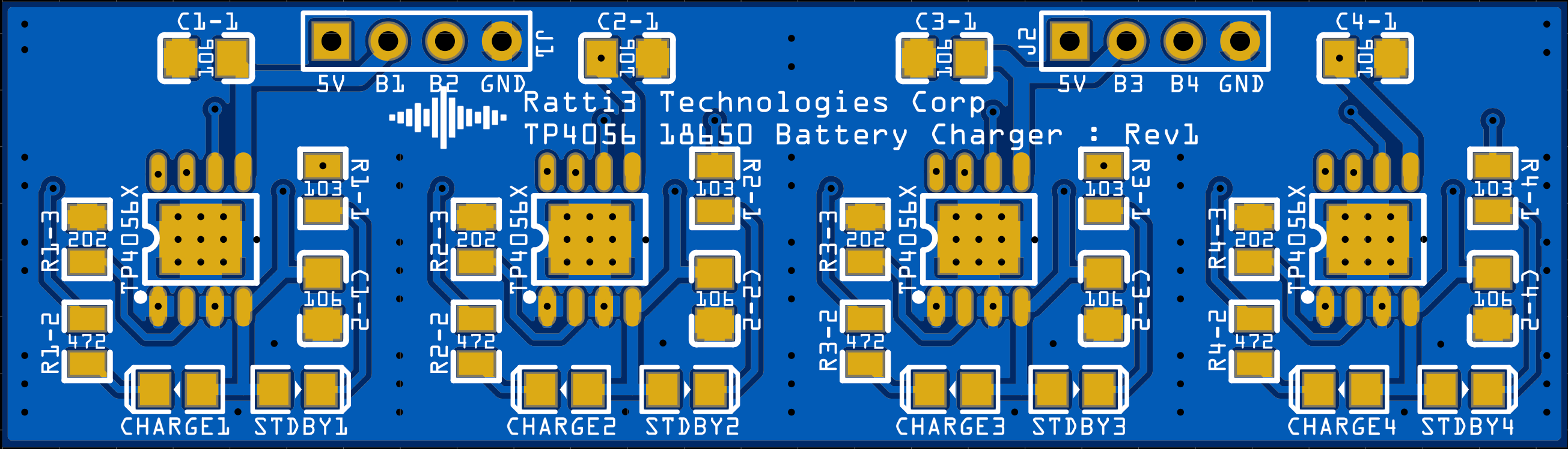 |
| Top side of the PCB. |
The rear of the PCB has space for six 11mm by 11mm heatsinks, there are no mounting holes so thermal glue has to be used.
 |
| Bottom side of the PCB. |
Each IC has a charge and standby LED.
The reason why the silkscreen text appears upside down is the module is meant to be mounted upside down in my amplifier.
Bill of Materials
|
Name |
Designator |
Qty |
Manufacturer Part |
Manufacturer |
Supplier |
Supplier Part |
|
KF301 5.0 6P |
AMP/SPEAKER |
1 |
PA001-6P |
HIWA |
LCSC |
C173288 |
|
LED-0805_R |
CHARGE3,CHARGE4 |
4 |
MHT170CRCT |
MEIHUA |
LCSC |
C389523 |
|
10uF |
C2-1,C4-2,C3-1,C3-2 |
8 |
CL21B106KOQNNNE |
SAMSUNG |
LCSC |
C95841 |
|
0.5R |
R2-4,R4-4,R3-4,R1-4 |
4 |
CSR2512FTR500 |
Stackpole Elec |
LCSC |
C346803 |
|
LED-0805_G |
STDBY2,STDBY1 |
4 |
MHT170UGCT |
MEIHUA |
LCSC |
C397047 |
|
2k |
R2-3,R1-3,R4-3,R3-3 |
4 |
RC0805FR-072KL |
YAGEO |
LCSC |
C114572 |
|
10k |
R2-1,R3-1,R4-1,R1-1 |
4 |
RC0805FR-071KL |
YAGEO |
LCSC |
C84376 |
|
4.7k |
R3-2,R1-2,R4-2,R2-2 |
4 |
AC0805FR-074K7L |
YAGEO |
LCSC |
C140869 |
|
HDR-M-2.54_1x4 |
J2,J1 |
2 |
LCSC |
C124378 |
||
|
TP4056 |
U2-1,U4-1,U3-1,U1-1 |
4 |
TP4056 |
TOPPOWER |
LCSC |
C191323 |
Additional components not in BOM:
Links
EasyEDA Project Page:
https://easyeda.com/Ratti3/tp4056-18650-li-ion-battery-charger
YouTube Video:
Image Gallery


Comments
Post a Comment