Dodgy over discharge voltages
 |
| The auto activation version |
I needed a battery protection board for my battery powered tube amplifier, I decided to buy several battery protection boards from Ebay, the reviews looked good and most of the boards seemed very popular.
Once I received and tested the boards I noticed a few problems:
All of them were using the ABLIC S-8254A IC, but the product code did not match the manufactureres datasheet, this led me to believe these ICs were fakes.
All apart from one board had to be activated by applying a charge current.
None of them had any mounting holes or headers.
Most were marked as battery management systems, they had no BMS function.
My biggest concern was the over discharge cutoff voltage of 2.5v, this is too low for most batteries and would damage the batteries. I was not planning on using the boards for charging and noticed the boards had a large tolerance on the over charge cutoff voltage, again this is not good.
I decided I did not want these pieces of crap in my project so I designed my own circuit with high quality components.
I designed two different version, the smaller circuit requires manual activation, the bigger circuit is auto activated by a relay when the batteries are connected.
The components
 |
| ABLICs part list |
The IC used is the ABLIC S-8254A, the version I chose is AWFT, this has a over discharge cutoff voltage of 3v. This is slightly above the batteries I'm going to use which is perfect.
Capacitors are C0G where posible, otherwise they are all X7R, the reason for using C0G is so there is not too much value change, as the voltage detections are based on timings using the capacitors.
It's the same with resistors, I've used 1% metal film with a temperature coefficient of ±100ppm/℃.
A small Omron 12v signal relay is used to activate the circuit.
The schematic
 |
| Standard Version |
The schematic is based on ABLICs datasheet, all default component values are supplied, the explanation on changing these values to achieve different cutoff voltages is very poor. However the default schematic is more than adequate and as I chose a specific IC, I got my desired over discharge cutoff voltage.
Lower power mosfets can be used if high output current is not required.
A power indicator LED has been added, this is optional.
Auto Activation Version:
 |
| Auto Activation |
The delay timing is done with capacitors C1 and C2, solid capacitors were chosen to ensure values don't change too much over time so delay timings remain unchanged.
 |
| Auto Activation Version |
Both schematics have NETS for doing a manual auto activation using a switch.
The calculations
The only calculations made were for the LEDs and for the transistor base resistors.
IB = Base Current
IC = Load Current (the relay used here uses about 9mA, we'll use a value of 25mA)
RB = Base Resistor
VIN = VCC (16.8v Max, 12.8v Min)
VBE = Base Emitter Voltage
β = hFE
Q3 to Q6 - BC846
β = from specsheet: 200 (this is the gain and is also known as hFE)
VBE = 0.7v
Q7 - MPSA92
β = from specsheet: 25
VBE = 0.7v
The base resistors for Q3 to Q6 are not too important as their load current is very low and they have a very high gain, so we can just choose a 100kΩ resistor which will be more than enough to saturate them.
This value also determines the additional quiescent current of the relay circuit (16.8v / 100,000 = 0.00016A).
To calculate R10 for Q7 we first need to work out the required base current (IB), to guarantee full saturation I added an extra 30% by multiplying the result by 1.3:
IC 0.025 mA
IB = ______ x 1.3 = __________ x 1.3 = 0.0013 mA
β 25
Now that we have the IB we now can work out RB (R10):
VIN - VBE 16.8 v - 0.7 v
RB = ___________ = _____________ = 12.38 kΩ
IB 0.0013 mA
A value of 10kΩ will be fine, the relay is only on for a couple of seconds.
High resistance values have been used for the LED resistors R12 and R13, as I did not want them to be too bright.
The PCB
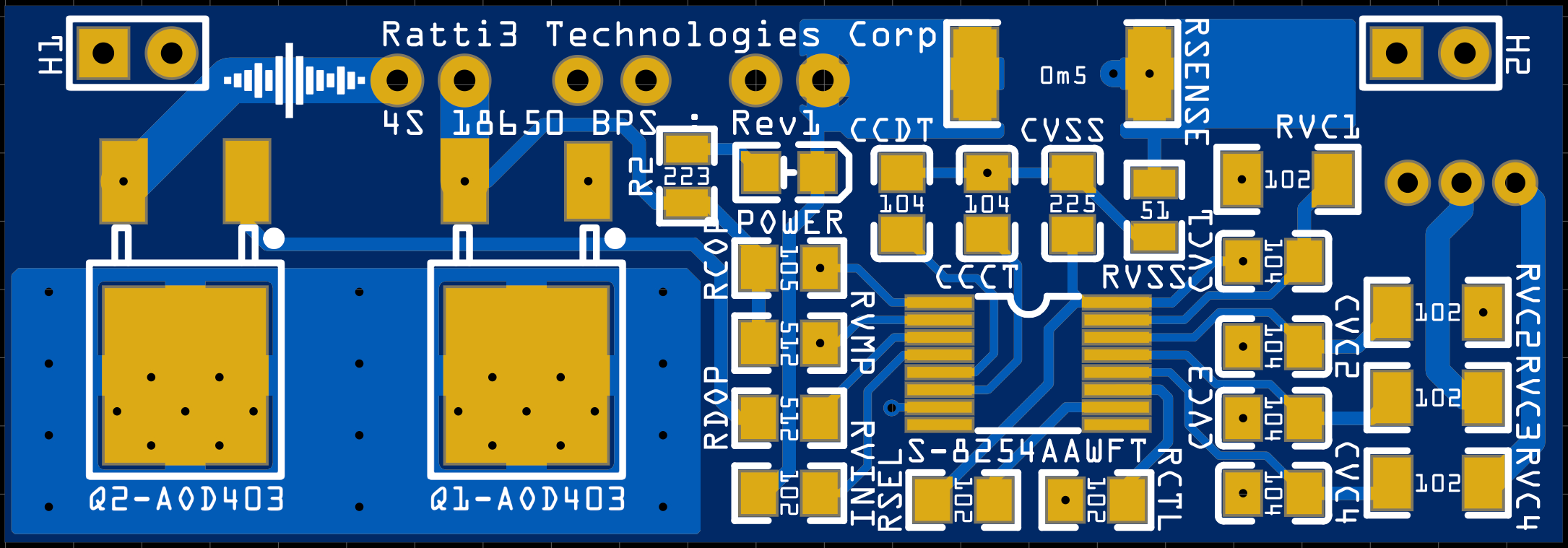 |
| Standard design, no auto activation, front |
The second board has some additional surface mount components on the rear along with the JST connectors.
 |
| Standard design, no auto activation, back |
 |
| With auto activation, front |
 |
| With auto activation, back |
Bill of Materials
|
Name |
Designator |
Qty |
Manufacturer Part |
Manufacturer |
Supplier |
Supplier Part |
|
1M |
RCOP |
1 |
RC0805FR-071ML |
YAGEO |
LCSC |
C107700 |
|
2.2uF |
CVSS |
1 |
CGA4J1X7R1V225KT0Y0E |
TDK |
LCSC |
C342739 |
|
22K |
R2 |
1 |
RC0805FR-0722KL |
YAGEO |
LCSC |
C114565 |
|
17-21/S2C-FR1S2L/3T |
POWER |
1 |
17-21/S2C-FR1S2L/3T |
Everlight Elec |
LCSC |
C264419 |
|
S-8254AAWFT-TB-G |
U1 |
1 |
S-8254AAWFT-TB-G |
ABLIC |
Mouser |
628-S-8254AAWFT-TB-G |
|
1K |
RVC2,RVC4,RVC3,RVC1 |
4 |
RC1206FR-071KL |
YAGEO |
LCSC |
C131398 |
|
AOD403 |
Q1,Q2 |
2 |
AOD403 |
AOS |
LCSC |
C28969 |
|
100nF |
CCCT,CCDT,CVC2 |
6 |
CGA4J2X7R1H104KT0Y0N |
TDK |
LCSC |
C415304 |
|
0.0005 |
RSENSE |
1 |
MA251220F0m50SZ |
Ever Ohms Tech |
LCSC |
C429364 |
|
XH-2AW |
CN-,CN+ |
2 |
XH-2AW |
BOOMELE |
LCSC |
C33132 |
|
51 |
RVSS |
1 |
AC0805FR-0751RL |
YAGEO |
LCSC |
C144556 |
|
PH-3A RHOS |
LMH |
1 |
PH-3A RHOS |
BOOMELE |
LCSC |
C2320 |
|
1K |
RVINI,RCTL,RSEL |
3 |
RC0805FR-071KL |
YAGEO |
LCSC |
C95781 |
|
MTP125-1102S1 |
H1,H2,RESET |
3 |
MTP125-1102S1 |
MINTRON |
LCSC |
C358684 |
|
5.1K |
RVMP,RDOP |
2 |
RC0805FR-075K1L |
YAGEO |
LCSC |
C84375 |
This specific ABLIC version seems to be only available with Mouser.
Links
EasyEDA Project Page:
https://easyeda.com/Ratti3/ablic-4s-18650-li-ion-battery-protection-system
https://easyeda.com/Ratti3/ablic-4s-18650-li-ion-battery-protection-system-with-auto-reset
YouTube Video:
Photo Gallery
Auto Activation version:


 |
| Mounted on my Tube AMP Board |
Standard Version:


Comments
Post a Comment