Experimental tube amplfier project
 |
| The completed amplifier |
The project started when I purchased a Fosi Audio T20 tube amplifier from Amazon, this was a polished hybrid tube amplifier with a TI power amplifier. I went on AliExpress and decided to purchase a bare PCB tube amplifier with an op-amp used for the headphone amplification. I was intrigued and decided to take it apart. The end result is this improved amplifier that runs on batteries.
The original schematic was based on a standard design and was nothing new, I found multiple examples based on this schematic, I made a few changes like adding a cathode resistor for a better bass response and adjusted the plate voltage and bias voltage.
Just to be clear this amplifier is not a true tube amplifier, the line input is fed into the EF95 tubes and amplified for the next stage, this is an op-amp which amplifies for the headphones. So technically speaking the tubes are adding their effect/distortion and this is then amplified by the op-amp.
It's also not hifi, but based in my testing and my 41 year old hearing it sounds great to me, I'm no audiophile but I have decent speaker/amplifier setups and headphones, I have to say this does sound good. I noticed changing the tubes and op-amp has an effect out the output sound.
 |
| The two different tube LEDs can be turned off. |
The battery module consists of a large PCB that hold 4x 18650 batteries, this board hold the components for providing a 4.6v supply to the TP4056 battery charging module, and a LDO linear regulator for converting the 16.8v from the 4S ABLIC s-8254 battery protection system to 12v.
Due to the requirements of voltage regulators, a heatsink is requred, this is added to the battery module PCB. I also decided to add a LM3914 battery level indicator, this is useful for keeping an eye on the individual battery voltages.
A bluetooth module, based on the Mh-M18 has been added as an input option.
The amplifier draws about 300mA and has a battery runtime of about eight hours. The amplifier can also be run from the mains, it can charge the batteries whilst you listen as well.
A DC power supply of 12V at 3.5Amp is required.
A total of six relays are used, two of the relays are used to isolate/connect the + power of the batteries, one is used to switch between DC and battery operation of the amplifier, another is used for the auto activation of the battery protection circuit and the two more are used for switching between bluetooth and line in and adding a delay before the headphones are connected to the output.
On the front we have a bluetooth switch with a blue LED, a red power indicator LED, a large logarithmic volume control, a on/off/charge toggle switch and the TP4056 charging module is visible so you can see the battery charging state.
On the left side we have the battery protection system with a power indicator LED.
The panel consists of gold plated line in/pre out RCA connectors, a 2.5mm x 5mm DC in, tube LED switch and three switches, one for running the amp on DC mains, disabling the battery charger and a battery protection reset switch which is not connected.
Note: See the other posts for more info on the modules mentioned below.
Videos of the amplifier.
Part 1
Part 3
Links
EasyEDA Projects:
Main Amp:
https://easyeda.com/Ratti3/ef95-6ak5-hybrid-tube-headphone-amplifier
Battery Board:
https://easyeda.com/Ratti3/ef95-6ak5-hybrid-tube-headphone-amplifier-4s-18650-module
S-8254 Battery Protection:
https://easyeda.com/Ratti3/ablic-4s-18650-li-ion-battery-protection-system-with-auto-reset
TP4056X Charging Module:
https://easyeda.com/Ratti3/tp4056x-18650-li-ion-battery-charger
LM3914 Battery Level Indicator:
https://easyeda.com/Ratti3/lm3914n-li-ion-adjustable-battery-level-meter
MH-M18 Bluetooth Receiver:
https://easyeda.com/Ratti3/mh-m18-bluetooth-audio-receiver-module
YouTube Videos:
S-8254 Battery Protection:
https://youtu.be/SwKMUWJow2g
TP4056X Charging Module:
https://youtu.be/Aoi0kJcRnSE
LM3914 Battery level Indicator:
https://youtu.be/u_-uY8or-Cc
The schematics
Main amplifier:
All the resistors are SMD, the capacitors chosen are all audio grade. The resistors have been adjusted to provide a plate voltage of 85V and a bias voltage of 1.35V. These values change depending on the EF95 tubes used.
 |
| Main amplifier |
100V booster:
All components used here are SMD, the schottky barrier diode is rated for 150V max. The circuit is configured to oscillate at 75KHz so it cannot be heard when listening to music. Output has fairly low ripple current. Two capacitors and resistors provide the ripple current filter on the output.
 |
| 100V booster |
Headphone start delay:
A three transistor configuration is used to add a delay (set by the capacitor value), so that the headphones are not connected immediately to the output.
 |
| Headphone start delay |
Input selector:
A simple relay circuit to control switching between line in and bluetooth.
 |
| Input selector |
LEDs:
Some cheeky LEDs under the tubes, two switchable colours, they can be turned off completely.
 |
| LEDs |
4S Battery Module:
This is the battery module PCB, it provides 4.6V for the TP4056 charging module, it converts the 16.8V from the battery protection system to 12V and holds the four 18650 batteries.
 |
| Battery module |
TP4056X Battery Charger:
This module charges the four 18650 batteries individually, cut-off voltage is 4.18V and charging current is 600mA.
 |
| TP4056X battery charger |
ABLIC S-8254 Battery Protection:
This module protects the batteries from over-discharging (3V), and shuts down if the batteries are unbalanced but does not balance the batteries.
 |
| S-8254 battery protection |
 |
| Auto Activation for the S-8254 |
LM3914N Battery Level Indicator:
This module is used to monitor the voltage of the four 18650 batteries individually, it can be calibrated to detect the min and max voltages of the batteries.
 |
| LM3914N battery level indicator |
MH-M18 Bluetooth Audio Receiver:
This module adds a simple bluetooth receiver to the amplifier, the additional components are there to remove ground loops and ripple current reduction.
 |
| MH-M18 bluetooth audio receiver |
The calculations
Check the posts on the individual modules to see the fomulas used for the UC3843, TP4056, S-8254 and the start delay circuits.
Thermal calculations for LM2596T:
VOUT = 4.63v (the desired output voltage)
VIN = 12v (supply voltage)
ILOAD = 2.5A (maximun load current)
IQ = 7.5mA (Quiescent Current)
VSAT = 1.2v (Saturation Voltage)
First we work out the duty cycle:
d (Duty Cycle) = VOUT/VIN
d = 4.63/12 = 0.386
Next we work out the power dissipated:
PD = (VIN x IQ) + d x ILOAD x VSAT
PD = (12 x 0.0075) + 0.386 x 2.5 x 1.2 = 1.43W
These are the known and assumed values needed to work out the junction temperature with and without a heatsink.
TJMAX = 125°C (max junction temperature of the regulator)
RθJA (Thermal Resistance Junction to Air) = 50°C/W
RθJC (Thermal Resistance Junction to Case) = 2°C/W
RθCS (Thermal Resistance Case to Heatsink) = 0.5°C/W
RθSA (Thermal Resistance Heatsink to Ambient) = 7°C/W
TA (Room Ambient Temperature) = 40°C <---- Using a higer value for worst case scenario
To work out the Junction Temperature with a 7°C/W heatsink:
TJ = PD (RθJC + RθCS + RθSA) + TA
TJ = 1.43 x (2 + 0.5 + 7) + 40 = 54°C
To work out the Junction Temperature without a heatsink:
TJ = (RθJA)(PD) + TA
TJ = (50 x 1.43) + 40 = 111.5°C <---- Junction temperature without heatsink, a bit toasty but possible.
Thermal calculations for MIC29300:
VOUT = 12v (output voltage)
VIN = 16.8v (max inout voltage)
IOUT = 500mA (max current used by amplifier)
To work out the power dissipated:
PD = IOUT (1.01(VIN - VOUT))
PD = 0.5 x (1.01 x (16.8 - 12) = 2.42W
These are the known and assumed values needed to work out the junction temperature with and without a heatsink.
TJMAX = 125°C
RθJC (Thermal Resistance Junction to Case) = 2°C/W
RθCS (Thermal Resistance Case to Heatsink) = 0.5°C/W
TA (Room Ambient Temperature) = 40°C
To work out the Thermal Resistance Heatsink to Ambient:
RθSA = ((TJMAX - TA) / PD) - (RθJC + RθCS)
RθSA = ((125 - 40) / 2.42) - (2 + 0.5) = 33°C/W <---- 33°C/W or lower heatsink required
To work out the Junction Temperature with Heatsink:
TJ = PD (RθJC + RθCS + RθSA) + TA
TJ = 2.42 x (2 + 0.5 + 7) + 40 = 63°C <---- 63°C Junction temperature with a 7°C/W heatsink
LM2596T adjustable resistor calculations:
VREF = 1.23V
R1 = 470R (MIN 240R : MAX 1.5K)
R2 = 1.3K
VOUT = VREF (1 + (R2/R1))
VOUT = 1.23 x (1 + (1300/470)) = 4.63V
These values produce the desired 4.63V needed by the TP4056X charging module.
The PCBs
The below images are the PCB layout, both the top and bottom are in a single image. The 3D models are also shown.
 |
| Main amp board |
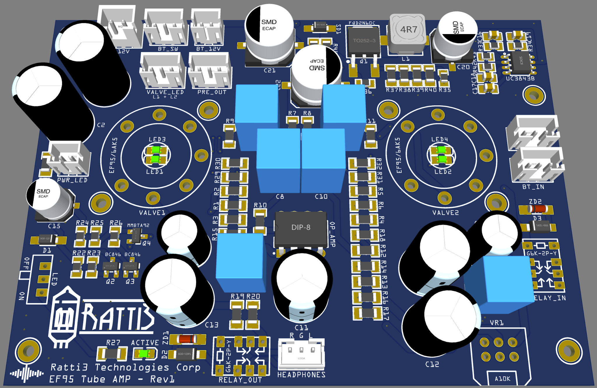 |
| Main amp board 3D model |
 |
| Battery board |
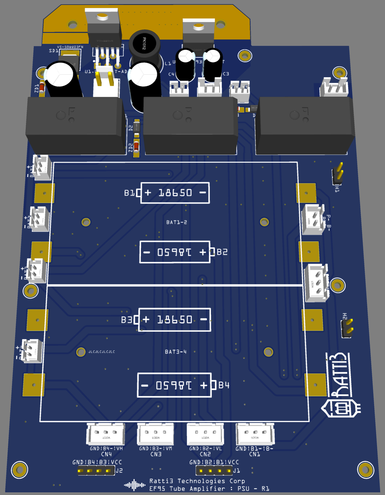 |
| Battery board 3D model |
 |
| LM3914 battery level indicator |
 |
| LM3914 battery level indicator 3D model |
 |
| MH-M18 bluetooth receiver |
 |
| MH-M18 bluetooth receiver 3D model |
 |
| Rear panel |
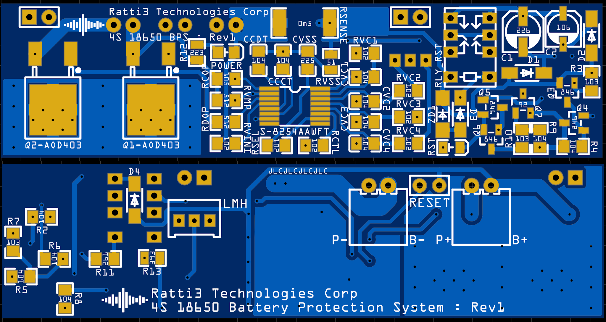 |
| S-8254 battery protection |
 |
| S-8254 battery protection 3D model |
 |
| TP4056X charging module |
 |
| TP4056X charging module 3D model |
The build
For the enclosure I decided to use Perspex, I like using tinted Perspex for electronics projects as I like to see the insides.
I did not use any special tools to make the case, just a tenon saw, a dremmel and a drill press along with some wet and dry sand paper.


Bill of materials
See the individual module blog posts for those BOMs.
This is the BOM for the main amplifier board:
|
Name |
Designator |
Qty |
Manufacturer Part |
Manufacturer |
Supplier |
Supplier Part |
|
47K |
R13,R14 |
2 |
RC1206FR-0747KL |
YAGEO |
LCSC |
C137270 |
|
4.7K |
R6,R3 |
2 |
RC1206FR-074K7L |
YAGEO |
LCSC |
C137262 |
|
56K |
R33 |
1 |
RC0805FR-0756KL |
YAGEO |
LCSC |
C137509 |
|
470K |
R4,R1 |
2 |
RC1206FR-07470KL |
YAGEO |
LCSC |
C137273 |
|
100nF |
C19 |
1 |
CGA4J2X7R2A104KT0Y0U |
TDK |
LCSC |
C342919 |
|
S115FA |
SD1 |
1 |
S115FA |
ON Semicon |
LCSC |
C258208 |
|
MHT170UGCT |
LED4,LED3 |
2 |
MHT170UGCT |
MEIHUA |
LCSC |
C397047 |
|
270 |
R2,R5 |
2 |
AC1206FR-07270RL |
YAGEO |
LCSC |
C229488 |
|
ZMM22 |
ZD2,ZD1 |
2 |
ZMM22 |
SEMTECH |
LCSC |
C8073 |
|
2.2 |
R38,R39,R40,R37 |
4 |
RC1206FR-072R2L |
YAGEO |
LCSC |
C137327 |
|
220u |
C13,C14,C12,C11 |
4 |
UFG1E221MPM |
Nichicon |
Mouser |
647-UFG1E221MPM |
|
100u |
C6,C5 |
2 |
UFG1E101MPM |
Nichicon |
Mouser |
647-UFG1E101MPM |
|
1.5K |
R18,R15 |
2 |
RC1206FR-071K5L |
YAGEO |
LCSC |
C114929 |
|
4.7nF |
C17 |
1 |
CGA4J3C0G2E472J125AA |
TDK |
LCSC |
C193083 |
|
2.2K |
R41 |
1 |
RC0805FR-072K2L |
YAGEO |
LCSC |
C114561 |
This is the BOM for the battery board:
|
Name |
Designator |
Qty |
Manufacturer Part |
Manufacturer |
Supplier |
Supplier Part |
|
LM2596T-ADJ/NOPB |
U1.LM2596T-ADJ |
1 |
LM2596T-ADJ/NOPB |
TI |
LCSC |
C21149 |
|
ZMM22 |
ZD3,ZD2,ZD1 |
3 |
ZMM22 |
SEMTECH |
LCSC |
C8073 |
|
MIC29300-12WT |
U3.MIC29300-12WT |
1 |
- |
Microchip Tech |
LCSC |
C14399 |
|
XH-3A |
CN1,BMS_HML,CN2,CN3,CN4 |
5 |
XH-3A |
BOOMELE |
LCSC |
C2316 |
|
VS-50WQ03FN-M3 |
SD1 |
1 |
VS-50WQ03FN-M3 |
Vishay Intertech |
LCSC |
C222476 |
|
330uF |
C2 |
1 |
EEUFC1V331 |
PANASONIC |
RS-Online |
315-0732 |
|
1N4002W |
D3,D1,D2 |
3 |
1N4002W |
Jingdao |
LCSC |
C169542 |
|
7447471470 |
L1 |
1 |
7447471330 |
Wurth Elektronik |
RS-Online |
749-8375 |
|
VH-2A |
12VDCIN |
1 |
VH-2A |
BOOMELE |
LCSC |
C16728 |
|
Relpol DPDT 12V 8A |
RL2,RL1,RL3 |
3 |
RM84-2012-35-1012 |
Relpol |
RS-Online |
123-2079 |
|
PH-2AK |
CHG_PWR,BAT2,BAT3 |
6 |
PH-2AK |
BOOMELE |
LCSC |
C8886 |
|
22uF |
C4,C3 |
2 |
EEUFC1J220 |
Panasonic |
RS-Online |
315-0940 |
|
XH-2A |
BMS+,BMS-,12VDC_OUT |
3 |
XH-2A |
BOOMELE |
LCSC |
C20079 |
|
1.3K |
R2 |
1 |
AC0805FR-071K3L |
YAGEO |
LCSC |
C144581 |
|
470R |
R1 |
1 |
AC0805FR-07470RL |
YAGEO |
LCSC |
C144560 |
Additional components not on above BOM:
Heatsink
Gold Plated RCA Connectors
DC Socket
Headphone Socket
LED Indicator
4PDT Switch
LED Switch
Mini Switch
18650 SMD Battery Holder
Knurled Aluminium Spacers
Tube Sockets
Aluminium Knob
Image Gallery


Can it be used with the speaker? Thank you Sir
ReplyDeleteNot passive speakers, the final amplification is done via an Op Amp, it won't be powerful enough. This is not a tube power amplifier.
ReplyDeleteThank you! Can you make a Russian electronic tubes speaker amplifier?
DeleteI could, it would require the higher power valves and a proper high voltage power supply. It would not be battery operated and would be bigger and completly different design. I don't have these valves and don't have any plans to make one. There are lots of examples of these amps on the internet. Thanks
DeleteWill it work with Ef91 tubes?
ReplyDeleteI don't think it will the Grid PINs are swapped, check here:
Deletehttp://www.r-type.org/exhib/aai0258.htm
http://www.r-type.org/exhib/aaa0215.htm
Can the S115FA be swapped out for a lower voltage Schottky diode lets say a 1N5819W.
DeleteSame with the ZMM22, the TCLLZ36V is a lot more accessible in my country.
1N5819W voltage is too low, needs to be at least 150V. Use mouser.co.uk to search for a suitable alternative:
Deletehttps://www.mouser.co.uk/c/semiconductors/discrete-semiconductors/diodes-rectifiers/schottky-diodes-rectifiers/?mounting%20style=SMD%2FSMT&package%20%2F%20case=SOD-123F-2~~SOD-123FL-2&vrrm%20-%20repetitive%20reverse%20voltage=150%20V&rp=semiconductors%2Fdiscrete-semiconductors%2Fdiodes-rectifiers%2Fschottky-diodes-rectifiers%7C~Package%20%2F%20Case
The TCLLZ36V will be fine, any Zener will do, a higher Zener voltage just affects the response time of the relay, in this case it won't cause a problem.
Okay so something like a SS10200HE_R1_00001 which is 200V? I also noticed that you used to different 100V diodes for D1,D2&D3 is there a specific reason or can I just go with 1N4002W for all three?
DeleteThe HV diode for the PSU looks good. The diodes on the relays are flybacks diode, some people use 1N4148 just on their own. I always try and go for the most optimal design or based on size of component and availability. Check here for more info: https://www.arrow.com/en/research-and-events/articles/flyback-protection-diodes
ReplyDelete1N4002 is fine.
Hi, the schematic says R2&R5 are 270 ohms but the soldermask 201 aka 200 ohms if you can just clarify.
DeleteRegards
Also can I swap out the FQD2N60CTM for a 500V IRFR420TRPBF?
DeleteI used 270R for R2, R5, the value can be changed if different tubes are used. IRFR420TRPBF should be fine, this one has a better RDS-On.
DeleteI want to remove the opamp so it becomes a preamplifier, is it possible?
ReplyDeleteYes, all the op amp surrounding components can be removed. Leaving just the preamp out capacitor and resistor. The gain from an EF95 may not be enough for your needs. It really depends on what you are trying to drive.
Deletethank you!!
DeleteHow does the button switch on the battery board work? I use four GND as one end, four B- as the common end, and the other four: VH, VM, VL and B- as the other end. Is that ok?
ReplyDelete