 |
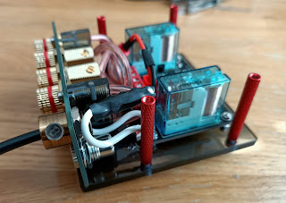
| Gold plated rear input and output banana sockets. |
Did I need to make this?
The schematic
The circuit consists of only three transistors and two power relays.
C1 is the delay capacitor, when it's charging Q2s base is deprived of current keeping it off and in turn keeping Q3 off, once C1 is charged Q2 starts conducting it turns on Q3 which in turn drives the relays.
 |
| EasyEDA Schematic |
I used common transistors and MPSA92 was chosen for its high voltage capability, this is because when the relays are de-energised they release their stored energy and this can build up quite a bit of a voltage on the transistors collector. Having the flyback diodes help with this and is a must. I opted for the relay diodes to be paired with a zener diode, this helps with the relay reponse times.
The choice of relay is dependant on the power being handled by them, DC is quite destructive to the relay contacts, if this was connected to a high power amp then the contacts on the relays over time may get degraded. I chose 16A Finder relays, they are overkill for my low power 50W amp, but they are transparent and look cool. It is important to connect the NC pins to speaker ground, will will prevent arcing inside the relay.
The Calculations
I don't have a formula for calculating the delay capacitor, but with a 33uF you get a 3 second delay with a 24v power supply, 22uF gives you about 2 seconds. D1 helps discharge the capacitor quickly.
Applying a positive voltage to the base of Q1 will turn off Q2 (and Q3). The relay can be a single 24v relay or in my case I've used two 12v relays in series.
The base resistors for the transistors need to be calculated to ensure they are saturated. Base resistor is calculated as follows:
IB = Base Current
IC = Load Current (the relays used here use about 40mA, we'll use a value of 50mA)
RB = Base Resistor
VIN
= VCC (24v)
VBE
= Base Emitter Voltage
β = hFE
Q1 and Q2
β = from specsheet: 200 (this is the gain and is also known as hFE)
VBE
= 0.7v
Q3 - MPSA92
β = from specsheet: 25
VBE
= 0.7v
The base resistors for Q1 and Q2 are not too important as their load current is very low and they have a very high gain, so we can just choose a 100kΩ resistor which will be more than enough to saturate them.
To calculate R5 and R6 for Q3 we first need to work out the required base current (IB), to guarantee full saturation I added an extra 30% by multiplying the result by 1.3:
IC 0.05 mA
IB = ______ x 1.3 = __________ x 1.3 = 0.0026 mA
β 25
Now that we have the IB we now can work out RB (R5 and R6):
VIN - VBE 24 v - 0.7 v
RB = ___________ = _____________ = 8.96 kΩ
IB 0.0026 mA
The closest value is 9.1kΩ you can use a single resistor, or in my case I've use two 18kΩ resistors in parallel to achieve 9kΩ.
The PCB
For the PCB design I used EasyEDA, for a free tool I find it very powerful and it has improved over time.
 |
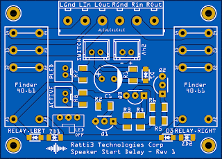
| The front of the PCB. |
The dimensions of the PCB is 64mm x 46mm.
I opted for suface mount resistors and diodes. All the trace widths for the relays are wide enough to handle high current if needed.
JST PH and XH connectors are used for the LEDs and power switch, with a micro toggle switch used to turn off/on the relay activation LED.
A 6 way PCB mouted screw terminal is used to connect up the speakers and amplifier.
A PCB was also used to hold all the connections at the rear.
 |
| The rear input/output panel. |
The Build
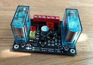
As I'm not mass producing this and with my limited amount of tools, I prefer to use 5mm or 3mm 9T20 Perspex sheets. It's easy to work with and very easy to cut and drill. It also looks cool when complete, as you can see insides.
 |
| PCB mounted on the perspex panels. |
Once my perspex sheets have been cut down to size, I sand them using wet fine grit (1200) sandpaper to get the smooth edges. I then use a drill press to get the holes made for the PCB mounts and the spacers.
The spacers are knurled aluminium used for RC toys.
Bill of Materials
|
Name |
Designator |
Qty |
Manufacturer Part |
Manufacturer |
Supplier |
Supplier Part |
|
KF301 5.0 6P |
AMP/SPEAKER |
1 |
PA001-6P |
HIWA |
LCSC |
C173288 |
|
ZMM24 |
ZD2,ZD1 |
2 |
ZMM24 |
SEMTECH |
LCSC |
C8074 |
|
FINDER 40.61.7.012.0000 |
RELAY.LEFT |
2 |
182-9781 |
Finder |
RS-Online |
40.61.7.012.0000 |
|
1N4002W |
D3,D2 |
2 |
1N4002W |
Jingdao |
LCSC |
C169542 |
|
XH-2A |
24V |
1 |
XH-2A red RHOS |
BOOMELE |
LCSC |
C24192 |
|
10K |
R8,R7,R2 |
3 |
RC1206FR-0710KL |
YAGEO |
LCSC |
C132649 |
|
91K |
R4 |
1 |
RC1206JR-0791KL |
YAGEO |
LCSC |
C137108 |
|
BC546BTA |
Q2,Q1 |
2 |
BC546BTA |
ON Semicon |
LCSC |
C258143 |
|
18K |
R6,R5 |
2 |
RC1206FR-0718KL |
YAGEO |
LCSC |
C137379 |
|
PH-2AK |
ACTIVE,PLED |
2 |
PH-2AK |
BOOMELE |
LCSC |
C8886 |
|
MPSA92-AT/P |
Q3 |
1 |
MPSA92-AT/P |
KEC |
LCSC |
C112896 |
|
33uF |
C1 |
1 |
PLV1H330MCL1 |
Nichicon |
RS-Online |
739-5396 |
|
XH-2A |
SWITCH |
1 |
xh-2ayellow |
BOOMELE |
LCSC |
C57141 |
|
MSK-12D19 |
NO |
1 |
K3-1260D-F1 |
Korean Hroparts Elec |
LCSC |
C223843 |
|
100K |
R3,R1 |
2 |
RC1206FR-07100KL |
YAGEO |
LCSC |
C137393 |
|
1N4148W-7-F |
D1 |
1 |
1N4148W-7-F |
DIODES |
LCSC |
C83528 |
Links
EasyEDA Project Page:
https://easyeda.com/Ratti3/speaker-start-delay-v2


Comments
Post a Comment