Arduino Nano 33 IoT Modular Nixie Clock with Web UI
USB 5V or 12V, Motion, Light, Temperature, Humidity & Pressure Sensors. NTP Sync, Web Interface for changing settings/time & wifi.

Project description
The story
*** Caution the PSU can output high DC voltages, can cause serious injury ***
I'm a bit late to the Nixie Party but I finally made it here.
This Nixie Clock is a bit different from the others; it runs using an Arduino Nano 33 IoT, has a motion sensor, light sensor, temperature, humidity & barometric pressure sensor and runs from 5V USB or 12V.
It has a web interface for changing settings and syncs the time using NTP.
Before I got to the final product, I had spent a lot of time making a Shift Register version with transistors and multiplexing, this worked on the breadboard however I got severe ghosting when I made the PCBs. I gave up and switched over to the HV5530 IC which simplifies things.
I had to devour a box of Mr Kipling cakes quickly so I could build the prototype:

Features and design
The clock has been made to be as modular as possible, the PCBs consist of a main Nixie board, Arduino Nano board with DS3231 and 12V boost convertor, HV PSU based on the TI UCC3803D that runs on 5V or 12V, a VEML7700 light sensor board, a BS612 PIR sensor board, a BME280 environmental sensor board and a power input board.
The modular design means modules can be interchanged with other future variations on this clock. I've already made a IN-12 version of clock.
The Nixies are driven using the Microchip HV5530 IC, this chip is capable of controlling each digit individually without having to multiplex.
It's designed to run from a 5V USB power supply or from a 12V wall plug.
When powering on the clock for the first time after a code upload, the Arduino will broadcast an AP SSID called NixieClock, the password is nixieclock and the default IP is 192.168.4.1.
Once you connect to this SSID, you can configure the clock by navigating to http://192.168.4.1, and connect to your own WiFi. The web interface additionally allows you to change various settings like brightness, NTP options, motion sensor, light sensor and date/time.
The clock is designed to turn the Nixies off when no one is in the room, this is achieved via the BS612 PIR sensor. A VEML7700 light sensor works along with the on/off schedule to determine if the clock needs to be turned off when it's night/bed time.
Every minute all the digits on the Nixies are cycled through using various patterns, this is to reduce cathode poisoning.
As the HV PSU is adjustable, the main Nixie board has trimmer potentiometers for adjusting the anode current.
The three buttons on the front are to display the date, environmental readings, IP address and setting the date/time manually.
YouTube video
Project links
Up to date schematics and BOM: https://easyeda.com/Ratti3
Code repository: https://github.com/Ratti3
Known issues
Updated 02-Aug-2022:
- On the IN-18 PCB, the VEML7700 light sensor can pick up the light from the Nixie, this can prevent the Nixies from turning off at night, the light level threshold can be adjusted accordingly to compensate for this or the sensor can be moved further back using 4 wires.
- The code is almost complete, I've not uploaded the latest version to GitHub yet, functions missing is the auto off based on the state of the sensors. Setting the time manually using the buttons, I think it gets stuck on setting the year, I'll look into that. You can set the time fine using the WebUI.
- It is recommened to use twisted wire pair for connecting the BME280 otherwise the Arduino can crash.
Tools required
I did have to buy several tools to make this clock, these include the following:

Belt & Disc Sander: https://www.vonhaus.com/vh_en/benchtop-belt-and-disc-sander
Bench Drill Press: https://www.amazon.co.uk/gp/product/B00766C1A8
Mini Bench Drill Press: https://www.amazon.co.uk/gp/product/B0012RQG94
Mini Belt Sander: https://www.amazon.co.uk/dp/B09YNPZ95T
Mini Table Saw: https://www.amazon.co.uk/gp/product/B07S3N9T7T
Rotary Multi Tool: https://www.amazon.co.uk/dp/B01N9GVO2L
Forstner Drill Bits: https://www.amazon.co.uk/gp/product/B072XJ5NG3
Clamps: https://www.amazon.co.uk/gp/product/B001C7LTSW
PCBs
All the PCBs have been designed with SMD components where possible. Board to board connections are done with low profile headers. Please note the part number of these headers are different on the BOM, the EasyEDA schematic mentions the correct part. Power, switch and I2C device connecions are done using JST connectors.
The Arduino PCB headers for the Arduino Nano are only partial, this is so the board could be made as small as possible, only the requried pins on the Arduino are soldered to match the header pins.
Some of the PCBs have large copper areas, as a result you will need a decent sodering iron to maintain the temperature when soldering components.
Nixie pins are the type that you see all over Ebay and are usually sold from China.
PCBs and Schematics can be found on the EasyEDA project page:
https://oshwlab.com/ratti3
Direct links:
https://oshwlab.com/Ratti3/in-18-hv5530-nixie-clock-shield
https://oshwlab.com/Ratti3/in-12-hv5530-nixie-clock-shield
https://oshwlab.com/Ratti3/arduino-nano-33-iot-shield-for-nixie-clock
https://oshwlab.com/ratti3/nixie-clock-ucc3803-5v-to-170v-power-supply-r2
https://oshwlab.com/ratti3/nixie-clock-ucc3803-5v-to-170v-power-supply-r4
https://oshwlab.com/ratti3/nixie-clock-usb-c-dc-power-board-r3
https://oshwlab.com/ratti3/nixie-clock-veml7700-light-sensor
https://oshwlab.com/ratti3/nixie-clock-bs612-pir-sensor
https://oshwlab.com/ratti3/nixie-clock-led-colon
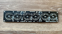 |
| The main board that holds the Nixies |
 |
| Underside of the main board |
 |
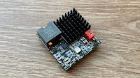
| The Arduino/DS3231/12V board with the Arduino Nano 33 IoT mounted |
 |
| Underside of the Arduino board, JST connectors for power and switches |
 |
| Arduino Board with the Arduino removed, note the gaps in the Arduino header pins. |
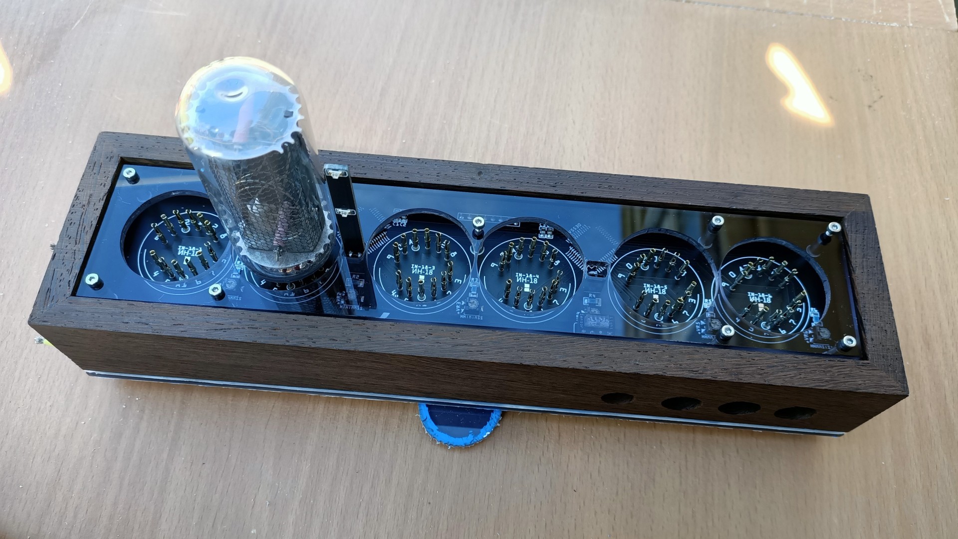
 |
Nixies mounted on the main board, the VEML7700 sits between tube 4 and 5 |
 |
Colon board, these are orange LEDs that are similar colour to the Nixies |
 |
VEML7700 I2C Light Sensor Board |


 |
BS612 PIR Sensor with adjustable timers |
 |
BME280 environmental sensor, I will make my own version soon |
 |
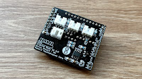
USB C and DC barrel jack power input |
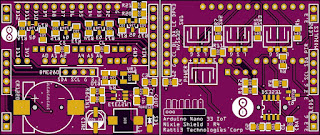
Here are some of the PCBs viewed from EasyEDA, safety precautions have been taken in to consideration, proper seperation between the HV and the other parts of the PCB have been added. All mounting holes are connected to ground:
 |
Main Nixie Board |

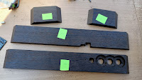
Building the case
I decided to use natural wood for the case, on Ebay you can buy 9-10mm thick off cuts ranging from Wengai, Oak, Maple, Ash etc. For this clock I chose Wengai, this is an African hardwood and originates from the Congo. It's a bit brittle, but with sharp woodworking tools, it's a pleasure work with.
The wood panels were cut with the mini circular saw, smoothed with the belt sander and the 45° corners were done using the belt sander. I used Gorilla Wood Glue to join all the pieces together, this glue is super strong and no additional fixings are requried.
I used 3mm 9T20 Mid Transparent Grey Perspex for the top and bottom.
 |
I used Wengai hardwood for the case, I got these 9mm thick planks from Ebay |
 |
Using Forstner Drill Bits for making holes for the switches. Using a drill press helps in getting precise results |
 |
The other side requires a larger Forstner bit to make a recessed hole |
 |
Switches and PIR sensor fit perfectly |
 |
The rear inside, as you can see there is a bigger recessed hole |
 |
The mini table saw was used to make this cutout for the power socket |
 |
All four pieces ready for glueing together |
 |
I used Gorilla Wood Glue and clamps to hold it together, screws not needed |
 |
The Wengai case assembled using just glue |
 |
I used 9T20 Gloss Mid Transparent Grey Perspex for the top and bottom, 1200 grit sandpaper for a smooth edge |
 |
I used a paper template (from EasyEDA PCB export) to mark cutout holes |
 |
Using the rotary mini tool to cut out holes using a 2.7mm HSS drill bit |
 |
Holes cut out, a sanding attachment was used to smooth the edges |
 |
Using a paper template (from EasyEDA PCB export), 2mm mounting holes were made |
 |
Making sure it all fits |
 |
The power socket fits perfectly in the case cutout |
 |
The bottom perspex of the case with all the mounting holes with M2 machine screws |
Assembly information
It it a good idea to use twised wires for the I2C devices, if you are running them to a different location inside the clock, this will preven the Arduino from crashing. I2C can be flaky.
The main PCB is mounted using M2 aluminium standoffs, these are available on Ebay and AliExpress in various colours and finish.
 |
The various custom made JST cables needed |
 |
Various fastenings are required, mostly M2 sizes screws and standoffs |
 |
Power interconnect and switch wires connected |
 |
Main power input connected on bottom right |
 |
Arduino and PSU board mounted to main Nixie board |
 |
It's easier to connect the switch side cables first before connecting to the Arduino, these are spade connectors |
 |
Cables attached, checking length to make sure there is no excess, long cables can cause the Arduino to crash |
 |
Connecting up the PIR sensor, this connects to the main board |
 |
Looks nice and tidy from the bottom, the BME280 is not connected here, I recommend using twisted cables for this |
 |
The LED colon boards mounted |
Web UI interface
The Web UI can be used to change WiFi, date/time, NTP, sensor and power settings. All changed made are saved to the Arduino flash.
 |
The WiFi config page |
 |
Display and brightness settings |
 |
Sensor related settings |
 |
Manual date/time adjust and NTP settings |
 |
Switch between 12V and 5V power supply, not setting this will not damage anything |
 |
Settings for changing the WebUI appearance and you can give the clock a name |
The code
The code was written using the Arduino IDE, due to the amount of code, I've used seperate.CPP and.H files.
The following libraries are required, everytime a library is updated and I'm updating the code, I test the latest version and mention it in the code. Currently the following libraries are required:
// v1.8.13 WiFi - https://github.com/arduino-libraries/WiFiNINA
#include <WiFiNINA.h>
// v1.8.13 WiFi UDP - https://github.com/arduino-libraries/WiFiNINA
#include <WiFiUdp.h>
// v3.2.1  NTP Client - https://github.com/arduino-libraries/NTPClient
#include <NTPClient.h>
// v1.0.0  Use Flash as EEPROM - https://github.com/cmaglie/FlashStorage
#include <FlashStorage.h>
// v2.0.3  DS3231 RTC - https://github.com/adafruit/RTClib
#include <RTClib.h>
// v1.1.5  Required by BME280 - https://github.com/adafruit/Adafruit_Sensor
#include <Adafruit_Sensor.h>
// v2.2.2  BME280 Environmental Sensor - https://github.com/adafruit/Adafruit_BME280_Library
#include <Adafruit_BME280.h>
// v2.1.1  VEML7700 Light Sensor - https://github.com/adafruit/Adafruit_VEML7700
#include <Adafruit_VEML7700.h>
// v1.9.2  Button - https://github.com/bxparks/AceButton
#include <AceButton.h>
The default AP password is located in the Secrets.h file:
#define WIFI_AP_SSID "NixieClock"
#define WIFI_AP_PASS "nixieclock"
Settings.h has some default values that are overwritten when using the Web UI, these can be changed if required:
// Store PWM HV5530 brightness level 1 - 255 (Note: 0 would turn off the Nixies but leave the HV on)
byte flashBrightness = 255;
// Store Enable/Disable NTP boolean
bool flashNTP = 1;
// Store NTP pool address (1 = africa, 2 = asia, 3 = europe, 4 = north america, 5 = oceania, 6 = south america)
byte flashNTPPool = 3;
// Store display On Hour
byte flashOnHour = 6;
// Store display Off hour
byte flashOffHour = 23;
// Store Enable/Disable PIR
bool flashPIR = 1;
// Store Enable/Disable Light Sensor
bool flashLight = 1;
// Set power supply mode, setting to 1 enables the 5v to 12v booster for the HV5530
bool flashUSB = 1;
// The WebUI font
byte flashFont = 1;
// The WebUI background
byte flashBackground = 4;
// UTC offset in hours
byte flashUTCOffset = 0;
// Colon LED Brightness via PWM
byte flashColon = 15;
// Switch 1-3 LED Brightness via PWM (note these values can be the same if the correct resistors are used for the LEDs)
byte flashLED1 = 180;
byte flashLED2 = 30;
byte flashLED3 = 170;
// Nixie Spin Cycles per minute
byte flashSpin = 1;
// Low Lux Level Threshold
byte flashLux = 1;
// Stores the NTP pool to query, changed via flashNTPPool
const char* ntpServerName = "europe.pool.ntp.org";
All the HTML for the Web UI is located in WiFiTask.cpp, there are no links to external images, all icons are done via SVG XML.
Parts not in the EasyEDA BOM
I should mention anything that is not part of the schematic won't be in the EasyEDA BOM. Here is a list of additional parts and components, I'll just mention the sites they can be found:
- 10mm LED low profile mometary push button switch [AliExpress/Ebay]
- Pre terminated wires with spade connectors for use with the 10mm switches, usually sold with the switches [AliExpress/Ebay]
- Wengai African Hardwood 9-10mm thick [Ebay]
- 3mm 9T20 Transparent Mid Grey Perspex [Ebay]
- Fresnel Lens [LCSC]
- Low profile female and male headers. Check EasyEDA schematic notes for part number
- JST plugs [LCSC]
- Nixie socket pins [AliExpress/Ebay]
- Nixie tubes [Ebay]
- Gorilla wood glue [Ebay]
- M2 Hex socket screws, washers, standoffs and nuts [AliExpress/Ebay]
- Silicon DC wires 22-26 AWG [Ebay]
- CR1220 lithium coin cell [Ebay]
- 25x25x10mm heatsink [AliExpress/Ebay]
- Thermal glue for heatsink [Amazon/Ebay]
- BME280 or BMP280 sensor (code adjustment may be required) [AliExpress/Ebay]
- 400, 600 and 1200 grit wet sandpaper [Local Hardware Store]
Hello, this is Liam from PCBWay.
ReplyDeleteDeeply impressed by your blog content which is novel and creative,
That being said, I would love to offer my support by sponsoring your project with free PCB prototyping.
All I ask for in return is a little bit of love - a slight promotion or review about our quality or service would be greatly appreciated.
What do you say? Are you interested in partnering up? Contact me: liam@pcbway.com
Hi, Liam you've contacted my a few times already (Hackaday). I'm good with paying for my own PCBs for now. Thanks
DeleteI rebuilt the clock and am fascinated how everything works. I still see a few software issues but then it's perfect. Are you planning to update the github code?
ReplyDeleteYes, there are some issues; however, I have new code but have not released it yet. I've been really busy with work and currently working on a KT88 power amplifier.
DeleteCan you send me the newer version? I would like to additionally integrate mqtt for control. It is not bad if there are still bugs, but maybe some are already fixed...
Delete